Drawing on Canvas
Browsers give us several ways to display graphics. The simplest way is to use styles to position and color regular DOM elements. This can get us quite far, as the game in the previous chapter showed. By adding partially transparent background images to the nodes, we can make them look exactly the way we want. It is even possible to rotate or skew nodes with the transform style.
But we’d be using the DOM for something that it wasn’t originally designed for. Some tasks, such as drawing a line between arbitrary points, are extremely awkward to do with regular HTML elements.
There are two alternatives. The first is DOM based but utilizes Scalable Vector Graphics (SVG) rather than HTML. Think of SVG as a document-markup dialect that focuses on shapes rather than text. You can embed an SVG document directly in an HTML document or include it with an <img> tag.
The second alternative is called a canvas. A canvas is a single DOM element that encapsulates a picture. It provides a programming interface for drawing shapes onto the space taken up by the node. The main difference between a canvas and an SVG picture is that in SVG the original description of the shapes is preserved so that they can be moved or resized at any time. A canvas, on the other hand, converts the shapes to pixels (colored dots on a raster) as soon as they are drawn and does not remember what these pixels represent. The only way to move a shape on a canvas is to clear the canvas (or the part of the canvas around the shape) and redraw it with the shape in a new position.
SVG
This book won’t go into SVG in detail, but I’ll briefly explain how it works. At the end of the chapter, I’ll come back to the trade-offs that you must consider when deciding which drawing mechanism is appropriate for a given application.
This is an HTML document with a simple SVG picture in it:
<p>Normal HTML here.</p>
<svg xmlns="http://www.w3.org/2000/svg">
  <circle r="50" cx="50" cy="50" fill="red"/>
  <rect x="120" y="5" width="90" height="90"
        stroke="blue" fill="none"/>
</svg>
The xmlns attribute changes an element (and its children) to a different XML namespace. This namespace, identified by a URL, specifies the dialect that we are currently speaking. The <circle> and <rect> tags, which do not exist in HTML, do have a meaning in SVG—they draw shapes using the style and position specified by their attributes.
These tags create DOM elements, just like HTML tags, that scripts can interact with. For example, this changes the <circle> element to be colored cyan instead:
let circle = document.querySelector("circle");
circle.setAttribute("fill", "cyan");
The canvas element
Canvas graphics can be drawn onto a <canvas> element. You can give such an element width and height attributes to determine its size in pixels.
A new canvas is empty, meaning it is entirely transparent and thus shows up as empty space in the document.
The <canvas> tag is intended to allow different styles of drawing. To get access to an actual drawing interface, we first need to create a context, an object whose methods provide the drawing interface. There are currently three widely supported drawing styles: "2d" for two-dimensional graphics, "webgl" for three-dimensional graphics through the OpenGL interface, and "webgpu", a more modern and flexible alternative to WebGL.
This book won’t discuss WebGL or WebGPU—we’ll stick to two dimensions. But if you are interested in three-dimensional graphics, I do encourage you to look into WebGPU. It provides a direct interface to graphics hardware and allows you to render even complicated scenes efficiently, using JavaScript.
You create a context with the getContext method on the <canvas> DOM element.
<p>Before canvas.</p>
<canvas width="120" height="60"></canvas>
<p>After canvas.</p>
<script>
  let canvas = document.querySelector("canvas");
  let context = canvas.getContext("2d");
  context.fillStyle = "red";
  context.fillRect(10, 10, 100, 50);
</script>
After creating the context object, the example draws a red rectangle that is 100 pixels wide and 50 pixels high, with its upper-left corner at coordinates (10, 10).
Just like in HTML (and SVG), the coordinate system that the canvas uses puts (0, 0) at the upper-left corner, and the positive y-axis goes down from there. This means (10, 10) is 10 pixels below and to the right of the upper-left corner.
Lines and surfaces
In the canvas interface, a shape can be filled, meaning its area is given a certain color or pattern, or it can be stroked, which means a line is drawn along its edge. SVG uses the same terminology.
The fillRect method fills a rectangle. It takes first the x- and y-coordinates of the rectangle’s upper-left corner, then its width, and then its height. A similar method called strokeRect draws the outline of a rectangle.
Neither method takes any further parameters. The color of the fill, thickness of the stroke, and so on, are not determined by an argument to the method, as you might reasonably expect, but rather by properties of the context object.
The fillStyle property controls the way shapes are filled. It can be set to a string that specifies a color, using the color notation used by CSS.
The strokeStyle property works similarly but determines the color used for a stroked line. The width of that line is determined by the lineWidth property, which may contain any positive number.
<canvas></canvas>
<script>
  let cx = document.querySelector("canvas").getContext("2d");
  cx.strokeStyle = "blue";
  cx.strokeRect(5, 5, 50, 50);
  cx.lineWidth = 5;
  cx.strokeRect(135, 5, 50, 50);
</script>
When no width or height attribute is specified, as in the example, a canvas element gets a default width of 300 pixels and height of 150 pixels.
Paths
A path is a sequence of lines. The 2D canvas interface takes a peculiar approach to describing such a path. It is done entirely through side effects. Paths are not values that can be stored and passed around. Instead, if you want to do something with a path, you make a sequence of method calls to describe its shape.
<canvas></canvas>
<script>
  let cx = document.querySelector("canvas").getContext("2d");
  cx.beginPath();
  for (let y = 10; y < 100; y += 10) {
    cx.moveTo(10, y);
    cx.lineTo(90, y);
  }
  cx.stroke();
</script>
This example creates a path with a number of horizontal line segments and then strokes it using the stroke method. Each segment created with lineTo starts at the path’s current position. That position is usually the end of the last segment, unless moveTo was called. In that case, the next segment would start at the position passed to moveTo.
When filling a path (using the fill method), each shape is filled separately. A path can contain multiple shapes—each moveTo motion starts a new one. But the path needs to be closed (meaning its start and end are in the same position) before it can be filled. If the path is not already closed, a line is added from its end to its start, and the shape enclosed by the completed path is filled.
<canvas></canvas>
<script>
  let cx = document.querySelector("canvas").getContext("2d");
  cx.beginPath();
  cx.moveTo(50, 10);
  cx.lineTo(10, 70);
  cx.lineTo(90, 70);
  cx.fill();
</script>
This example draws a filled triangle. Note that only two of the triangle’s sides are explicitly drawn. The third, from the lower-right corner back to the top, is implied and wouldn’t be there if you stroked the path.
You could also use the closePath method to explicitly close a path by adding an actual line segment back to the path’s start. This segment is drawn when stroking the path.
Curves
A path may also contain curved lines. These are unfortunately a bit more involved to draw.
The quadraticCurveTo method draws a curve to a given point. To determine the curvature of the line, the method is given a control point as well as a destination point. Imagine this control point as attracting the line, giving it its curve. The line won’t go through the control point, but its direction at the start and end points will be such that a straight line in that direction would point toward the control point. The following example illustrates this:
<canvas></canvas>
<script>
  let cx = document.querySelector("canvas").getContext("2d");
  cx.beginPath();
  cx.moveTo(10, 90);
  // control=(60, 10) goal=(90, 90)
  cx.quadraticCurveTo(60, 10, 90, 90);
  cx.lineTo(60, 10);
  cx.closePath();
  cx.stroke();
</script>
We draw a quadratic curve from the left to the right, with (60, 10) as the control point, and then draw two line segments going through that control point and back to the start of the line. The result somewhat resembles a Star Trek insignia. You can see the effect of the control point: the lines leaving the lower corners start off in the direction of the control point and then curve toward their target.
The bezierCurveTo method draws a similar kind of curve. Instead of a single control point, this method has two—one for each of the line’s end points. Here is a similar sketch to illustrate the behavior of such a curve:
<canvas></canvas>
<script>
  let cx = document.querySelector("canvas").getContext("2d");
  cx.beginPath();
  cx.moveTo(10, 90);
  // control1=(10, 10) control2=(90, 10) goal=(50, 90)
  cx.bezierCurveTo(10, 10, 90, 10, 50, 90);
  cx.lineTo(90, 10);
  cx.lineTo(10, 10);
  cx.closePath();
  cx.stroke();
</script>
The two control points specify the direction at both ends of the curve. The farther they are away from their corresponding point, the more the curve will “bulge” in that direction.
Such curves can be hard to work with—it’s not always clear how to find the control points that provide the shape you are looking for. Sometimes you can compute them, and sometimes you’ll just have to find a suitable value by trial and error.
The arc method is a way to draw a line that curves along the edge of a circle. It takes a pair of coordinates for the arc’s center, a radius, and then a start angle and end angle.
Those last two parameters make it possible to draw only part of the circle. The angles are measured in radians, not degrees. This means a full circle has an angle of 2π, or 2 * Math.PI, which is about 6.28. The angle starts counting at the point to the right of the circle’s center and goes clockwise from there. You can use a start of 0 and an end bigger than 2π (say, 7) to draw a full circle.
<canvas></canvas>
<script>
  let cx = document.querySelector("canvas").getContext("2d");
  cx.beginPath();
  // center=(50, 50) radius=40 angle=0 to 7
  cx.arc(50, 50, 40, 0, 7);
  // center=(150, 50) radius=40 angle=0 to ½π
  cx.arc(150, 50, 40, 0, 0.5 * Math.PI);
  cx.stroke();
</script>
The resulting picture contains a line from the right of the full circle (first call to arc) to the right of the quarter-circle (second call).
Like other path-drawing methods, a line drawn with arc is connected to the previous path segment.You can call moveTo or start a new path to avoid this.
Drawing a pie chart
Imagine you’ve just taken a job at EconomiCorp, Inc. Your first assignment is to draw a pie chart of its customer satisfaction survey results.
The results binding contains an array of objects that represent the survey responses.
const results = [
  {name: "Satisfied", count: 1043, color: "lightblue"},
  {name: "Neutral", count: 563, color: "lightgreen"},
  {name: "Unsatisfied", count: 510, color: "pink"},
  {name: "No comment", count: 175, color: "silver"}
];
To draw a pie chart, we draw a number of pie slices, each made up of an arc and a pair of lines to the center of that arc. We can compute the angle taken up by each arc by dividing a full circle (2π) by the total number of responses and then multiplying that number (the angle per response) by the number of people who picked a given choice.
<canvas width="200" height="200"></canvas>
<script>
  let cx = document.querySelector("canvas").getContext("2d");
  let total = results
    .reduce((sum, {count}) => sum + count, 0);
  // Start at the top
  let currentAngle = -0.5 * Math.PI;
  for (let result of results) {
    let sliceAngle = (result.count / total) * 2 * Math.PI;
    cx.beginPath();
    // center=100,100, radius=100
    // from current angle, clockwise by slice's angle
    cx.arc(100, 100, 100,
           currentAngle, currentAngle + sliceAngle);
    currentAngle += sliceAngle;
    cx.lineTo(100, 100);
    cx.fillStyle = result.color;
    cx.fill();
  }
</script>
But a chart that doesn’t tell us what the slices mean isn’t very helpful. We need a way to draw text to the canvas.
Text
A 2D canvas drawing context provides the methods fillText and strokeText. The latter can be useful for outlining letters, but usually fillText is what you need. It will fill the outline of the given text with the current fillStyle.
<canvas></canvas>
<script>
  let cx = document.querySelector("canvas").getContext("2d");
  cx.font = "28px Georgia";
  cx.fillStyle = "fuchsia";
  cx.fillText("I can draw text, too!", 10, 50);
</script>
You can specify the size, style, and font of the text with the font property. This example just gives a font size and family name. It is also possible to add italic or bold to the start of the string to select a style.
The last two arguments to fillText and strokeText provide the position at which the font is drawn. By default, they indicate the position of the start of the text’s alphabetic baseline, which is the line that letters “stand” on, not counting hanging parts in letters such as j or p. You can change the horizontal position by setting the textAlign property to "end" or "center" and the vertical position by setting textBaseline to "top", "middle", or "bottom".
We’ll come back to our pie chart, and the problem of labeling the slices, in the exercises at the end of the chapter.
Images
In computer graphics, a distinction is often made between vector graphics and bitmap graphics. The first is what we have been doing so far in this chapter—specifying a picture by giving a logical description of shapes. Bitmap graphics, on the other hand, don’t specify actual shapes but rather work with pixel data (rasters of colored dots).
The drawImage method allows us to draw pixel data onto a canvas. This pixel data can originate from an <img> element or from another canvas. The following example creates a detached <img> element and loads an image file into it. But the method cannot immediately start drawing from this picture because the browser may not have loaded it yet. To deal with this, we register a "load" event handler and do the drawing after the image has loaded.
<canvas></canvas>
<script>
  let cx = document.querySelector("canvas").getContext("2d");
  let img = document.createElement("img");
  img.src = "img/hat.png";
  img.addEventListener("load", () => {
    for (let x = 10; x < 200; x += 30) {
      cx.drawImage(img, x, 10);
    }
  });
</script>
By default, drawImage will draw the image at its original size. You can also give it two additional arguments to specify the width and height of the drawn image, when those aren’t the same as the origin image.
When drawImage is given nine arguments, it can be used to draw only a fragment of an image. The second through fifth arguments indicate the rectangle (x, y, width, and height) in the source image that should be copied, and the sixth to ninth arguments give the rectangle (on the canvas) into which it should be copied.
This can be used to pack multiple sprites (image elements) into a single image file and then draw only the part you need. For example, this picture contains a game character in multiple poses:
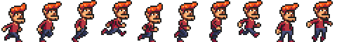
By alternating which pose we draw, we can show an animation that looks like a walking character.
To animate a picture on a canvas, the clearRect method is useful. It resembles fillRect, but instead of coloring the rectangle, it makes it transparent, removing the previously drawn pixels.
We know that each sprite, each subpicture, is 24 pixels wide and 30 pixels high. The following code loads the image and then sets up an interval (repeated timer) to draw the next frame:
<canvas></canvas>
<script>
  let cx = document.querySelector("canvas").getContext("2d");
  let img = document.createElement("img");
  img.src = "img/player.png";
  let spriteW = 24, spriteH = 30;
  img.addEventListener("load", () => {
    let cycle = 0;
    setInterval(() => {
      cx.clearRect(0, 0, spriteW, spriteH);
      cx.drawImage(img,
                   // source rectangle
                   cycle * spriteW, 0, spriteW, spriteH,
                   // destination rectangle
                   0,               0, spriteW, spriteH);
      cycle = (cycle + 1) % 8;
    }, 120);
  });
</script>
The cycle binding tracks our position in the animation. For each frame, it is incremented and then clipped back to the 0 to 7 range by using the remainder operator. This binding is then used to compute the x-coordinate that the sprite for the current pose has in the picture.
Transformation
What if we want our character to walk to the left instead of to the right? We could draw another set of sprites, of course. But we could also instruct the canvas to draw the picture the other way round.
Calling the scale method will cause anything drawn after it to be scaled. This method takes two parameters, one to set a horizontal scale and one to set a vertical scale.
<canvas></canvas>
<script>
  let cx = document.querySelector("canvas").getContext("2d");
  cx.scale(3, .5);
  cx.beginPath();
  cx.arc(50, 50, 40, 0, 7);
  cx.lineWidth = 3;
  cx.stroke();
</script>
Scaling will cause everything about the drawn image, including the line width, to be stretched out or squeezed together as specified. Scaling by a negative amount will flip the picture around. The flipping happens around point (0, 0), which means it will also flip the direction of the coordinate system. When a horizontal scaling of -1 is applied, a shape drawn at x position 100 will end up at what used to be position -100.
To turn a picture around, we can’t simply add cx.scale(-1, 1) before the call to drawImage. That would move our picture outside of the canvas, where it won’t be visible. We could adjust the coordinates given to drawImage to compensate for this by drawing the image at x position -50 instead of 0. Another solution, which doesn’t require the code doing the drawing to know about the scale change, is to adjust the axis around which the scaling happens.
There are several other methods besides scale that influence the coordinate system for a canvas. You can rotate subsequently drawn shapes with the rotate method and move them with the translate method. The interesting—and confusing—thing is that these transformations stack, meaning that each one happens relative to the previous transformations.
If we translate by 10 horizontal pixels twice, everything will be drawn 20 pixels to the right. If we first move the center of the coordinate system to (50, 50) and then rotate by 20 degrees (about 0.1π radians), that rotation will happen around point (50, 50).

But if we first rotate by 20 degrees and then translate by (50, 50), the translation will happen in the rotated coordinate system and thus produce a different orientation. The order in which transformations are applied matters.
To flip a picture around the vertical line at a given x position, we can do the following:
function flipHorizontally(context, around) {
  context.translate(around, 0);
  context.scale(-1, 1);
  context.translate(-around, 0);
}
We move the y-axis to where we want our mirror to be, apply the mirroring, and finally move the y-axis back to its proper place in the mirrored universe. The following picture explains why this works:

This shows the coordinate systems before and after mirroring across the central line. The triangles are numbered to illustrate each step. If we draw a triangle at a positive x position, it would, by default, be in the place where triangle 1 is. A call to flipHorizontally first does a translation to the right, which gets us to triangle 2. It then scales, flipping the triangle over to position 3. This is not where it should be, if it were mirrored in the given line. The second translate call fixes this—it “cancels” the initial translation and makes triangle 4 appear exactly where it should.
We can now draw a mirrored character at position (100, 0) by flipping the world around the character’s vertical center.
<canvas></canvas>
<script>
  let cx = document.querySelector("canvas").getContext("2d");
  let img = document.createElement("img");
  img.src = "img/player.png";
  let spriteW = 24, spriteH = 30;
  img.addEventListener("load", () => {
    flipHorizontally(cx, 100 + spriteW / 2);
    cx.drawImage(img, 0, 0, spriteW, spriteH,
                 100, 0, spriteW, spriteH);
  });
</script>
Storing and clearing transformations
Transformations stick around. Everything else we draw after drawing that mirrored character would also be mirrored. That might be inconvenient.
It is possible to save the current transformation, do some drawing and transforming, and then restore the old transformation. This is usually the proper thing to do for a function that needs to temporarily transform the coordinate system. First, we save whatever transformation the code that called the function was using. Then the function does its thing, adding more transformations on top of the current transformation. Finally, we revert to the transformation we started with.
The save and restore methods on the 2D canvas context do this transformation management. They conceptually keep a stack of transformation states. When you call save, the current state is pushed onto the stack, and when you call restore, the state on top of the stack is taken off and used as the context’s current transformation. You can also call resetTransform to fully reset the transformation.
The branch function in the following example illustrates what you can do with a function that changes the transformation and then calls a function (in this case itself), which continues drawing with the given transformation.
This function draws a treelike shape by drawing a line, moving the center of the coordinate system to the end of the line, and calling itself twice—first rotated to the left and then rotated to the right. Every call reduces the length of the branch drawn, and the recursion stops when the length drops below 8.
<canvas width="600" height="300"></canvas>
<script>
  let cx = document.querySelector("canvas").getContext("2d");
  function branch(length, angle, scale) {
    cx.fillRect(0, 0, 1, length);
    if (length < 8) return;
    cx.save();
    cx.translate(0, length);
    cx.rotate(-angle);
    branch(length * scale, angle, scale);
    cx.rotate(2 * angle);
    branch(length * scale, angle, scale);
    cx.restore();
  }
  cx.translate(300, 0);
  branch(60, 0.5, 0.8);
</script>
If the calls to save and restore were not there, the second recursive call to branch would end up with the position and rotation created by the first call. It would be connected not to the current branch but rather to the innermost, rightmost branch drawn by the first call. The resulting shape might also be interesting, but it is definitely not a tree.
Back to the game
We now know enough about canvas drawing to start working on a canvas-based display system for the game from the previous chapter. The new display will no longer be showing just colored boxes. Instead, we’ll use drawImage to draw pictures that represent the game’s elements.
We define another display object type called CanvasDisplay, supporting the same interface as DOMDisplay from Chapter 16—namely, the methods syncState and clear.
This object keeps a little more information than DOMDisplay. Rather than using the scroll position of its DOM element, it tracks its own viewport, which tells us which part of the level we are currently looking at. Finally, it keeps a flipPlayer property so that even when the player is standing still, it keeps facing the direction in which it last moved.
class CanvasDisplay {
  constructor(parent, level) {
    this.canvas = document.createElement("canvas");
    this.canvas.width = Math.min(600, level.width * scale);
    this.canvas.height = Math.min(450, level.height * scale);
    parent.appendChild(this.canvas);
    this.cx = this.canvas.getContext("2d");

    this.flipPlayer = false;

    this.viewport = {
      left: 0,
      top: 0,
      width: this.canvas.width / scale,
      height: this.canvas.height / scale
    };
  }

  clear() {
    this.canvas.remove();
  }
}
The syncState method first computes a new viewport and then draws the game scene at the appropriate position.
CanvasDisplay.prototype.syncState = function(state) {
  this.updateViewport(state);
  this.clearDisplay(state.status);
  this.drawBackground(state.level);
  this.drawActors(state.actors);
};
Contrary to DOMDisplay, this display style does have to redraw the background on every update. Because shapes on a canvas are just pixels, after we draw them there is no good way to move them (or remove them). The only way to update the canvas display is to clear it and redraw the scene. We may also have scrolled, which requires the background to be in a different position.
The updateViewport method is similar to DOMDisplay’s scrollPlayerIntoView method. It checks whether the player is too close to the edge of the screen and moves the viewport when this is the case.
CanvasDisplay.prototype.updateViewport = function(state) {
  let view = this.viewport, margin = view.width / 3;
  let player = state.player;
  let center = player.pos.plus(player.size.times(0.5));

  if (center.x < view.left + margin) {
    view.left = Math.max(center.x - margin, 0);
  } else if (center.x > view.left + view.width - margin) {
    view.left = Math.min(center.x + margin - view.width,
                         state.level.width - view.width);
  }
  if (center.y < view.top + margin) {
    view.top = Math.max(center.y - margin, 0);
  } else if (center.y > view.top + view.height - margin) {
    view.top = Math.min(center.y + margin - view.height,
                        state.level.height - view.height);
  }
};
The calls to Math.max and Math.min ensure that the viewport does not end up showing space outside of the level. Math.max(x, 0) makes sure the resulting number is not less than zero. Math.min similarly guarantees that a value stays below a given bound.
When clearing the display, we’ll use a slightly different color depending on whether the game is won (brighter) or lost (darker).
CanvasDisplay.prototype.clearDisplay = function(status) {
  if (status == "won") {
    this.cx.fillStyle = "rgb(68, 191, 255)";
  } else if (status == "lost") {
    this.cx.fillStyle = "rgb(44, 136, 214)";
  } else {
    this.cx.fillStyle = "rgb(52, 166, 251)";
  }
  this.cx.fillRect(0, 0,
                   this.canvas.width, this.canvas.height);
};
To draw the background, we run through the tiles that are visible in the current viewport, using the same trick used in the touches method from the previous chapter.
let otherSprites = document.createElement("img");
otherSprites.src = "img/sprites.png";

CanvasDisplay.prototype.drawBackground = function(level) {
  let {left, top, width, height} = this.viewport;
  let xStart = Math.floor(left);
  let xEnd = Math.ceil(left + width);
  let yStart = Math.floor(top);
  let yEnd = Math.ceil(top + height);

  for (let y = yStart; y < yEnd; y++) {
    for (let x = xStart; x < xEnd; x++) {
      let tile = level.rows[y][x];
      if (tile == "empty") continue;
      let screenX = (x - left) * scale;
      let screenY = (y - top) * scale;
      let tileX = tile == "lava" ? scale : 0;
      this.cx.drawImage(otherSprites,
                        tileX,         0, scale, scale,
                        screenX, screenY, scale, scale);
    }
  }
};
Tiles that are not empty are drawn with drawImage. The otherSprites image contains the pictures used for elements other than the player. It contains, from left to right, the wall tile, the lava tile, and the sprite for a coin.
Background tiles are 20 by 20 pixels, since we’ll use the same scale as in DOMDisplay. Thus, the offset for lava tiles is 20 (the value of the scale binding), and the offset for walls is 0.
We don’t bother waiting for the sprite image to load. Calling drawImage with an image that hasn’t been loaded yet will simply do nothing. Thus, we might fail to draw the game properly for the first few frames while the image is still loading, but that isn’t a serious problem. Since we keep updating the screen, the correct scene will appear as soon as the loading finishes.
The walking character shown earlier will be used to represent the player. The code that draws it needs to pick the right sprite and direction based on the player’s current motion. The first eight sprites contain a walking animation. When the player is moving along a floor, we cycle through them based on the current time. We want to switch frames every 60 milliseconds, so the time is divided by 60 first. When the player is standing still, we draw the ninth sprite. During jumps, which are recognized by the fact that the vertical speed is not zero, we use the tenth, rightmost sprite.
Because the sprites are slightly wider than the player object—24 instead of 16 pixels to allow some space for feet and arms—the method has to adjust the x-coordinate and width by a given amount (playerXOverlap).
let playerSprites = document.createElement("img");
playerSprites.src = "img/player.png";
const playerXOverlap = 4;

CanvasDisplay.prototype.drawPlayer = function(player, x, y,
                                              width, height){
  width += playerXOverlap * 2;
  x -= playerXOverlap;
  if (player.speed.x != 0) {
    this.flipPlayer = player.speed.x < 0;
  }

  let tile = 8;
  if (player.speed.y != 0) {
    tile = 9;
  } else if (player.speed.x != 0) {
    tile = Math.floor(Date.now() / 60) % 8;
  }

  this.cx.save();
  if (this.flipPlayer) {
    flipHorizontally(this.cx, x + width / 2);
  }
  let tileX = tile * width;
  this.cx.drawImage(playerSprites, tileX, 0, width, height,
                                   x,     y, width, height);
  this.cx.restore();
};
The drawPlayer method is called by drawActors, which is responsible for drawing all the actors in the game.
CanvasDisplay.prototype.drawActors = function(actors) {
  for (let actor of actors) {
    let width = actor.size.x * scale;
    let height = actor.size.y * scale;
    let x = (actor.pos.x - this.viewport.left) * scale;
    let y = (actor.pos.y - this.viewport.top) * scale;
    if (actor.type == "player") {
      this.drawPlayer(actor, x, y, width, height);
    } else {
      let tileX = (actor.type == "coin" ? 2 : 1) * scale;
      this.cx.drawImage(otherSprites,
                        tileX, 0, width, height,
                        x,     y, width, height);
    }
  }
};
When drawing something that is not the player, we look at its type to find the offset of the correct sprite. The lava tile is found at offset 20, and the coin sprite is found at 40 (two times scale).
We have to subtract the viewport’s position when computing the actor’s position, since (0, 0) on our canvas corresponds to the top left of the viewport, not the top left of the level. We could also have used translate for this. Either way works.
This document plugs the new display into runGame:
<body>
  <script>
    runGame(GAME_LEVELS, CanvasDisplay);
  </script>
</body>
Choosing a graphics interface
When you need to generate graphics in the browser, you can choose between plain HTML, SVG, and canvas. There is no single best approach that works in all situations. Each option has strengths and weaknesses.
Plain HTML has the advantage of being simple. It also integrates well with text. Both SVG and canvas allow you to draw text, but they won’t help you position that text or wrap it when it takes up more than one line. In an HTML-based picture, it is much easier to include blocks of text.
SVG can be used to produce crisp graphics that look good at any zoom level. Unlike HTML, it is designed for drawing and is thus more suitable for that purpose.
Both SVG and HTML build up a data structure (the DOM) that represents your picture. This makes it possible to modify elements after they are drawn. If you need to repeatedly change a small part of a big picture in response to what the user is doing or as part of an animation, doing it in a canvas can be needlessly expensive. The DOM also allows us to register mouse event handlers on every element in the picture (even on shapes drawn with SVG). You can’t do that with canvas.
But canvas’s pixel-oriented approach can be an advantage when drawing a huge number of tiny elements. The fact that it does not build up a data structure but only repeatedly draws onto the same pixel surface gives canvas a lower cost per shape. There are also effects that are only practical with a canvas element, such as rendering a scene one pixel at a time (for example, using a ray tracer) or postprocessing an image with JavaScript (blurring or distorting it).
In some cases, you may want to combine several of these techniques. For example, you might draw a graph with SVG or canvas but show textual information by positioning an HTML element on top of the picture.
For nondemanding applications, it really doesn’t matter much which interface you choose. The display we built for our game in this chapter could have been implemented using any of these three graphics technologies, since it does not need to draw text, handle mouse interaction, or work with an extraordinarily large number of elements.
Summary
In this chapter we discussed techniques for drawing graphics in the browser, focusing on the <canvas> element.
A canvas node represents an area in a document that our program may draw on. This drawing is done through a drawing context object, created with the getContext method.
The 2D drawing interface allows us to fill and stroke various shapes. The context’s fillStyle property determines how shapes are filled. The strokeStyle and lineWidth properties control the way lines are drawn.
Rectangles and pieces of text can be drawn with a single method call. The fillRect and strokeRect methods draw rectangles, and the fillText and strokeText methods draw text. To create custom shapes, we must first build up a path.
Calling beginPath starts a new path. A number of other methods add lines and curves to the current path. For example, lineTo can add a straight line. When a path is finished, it can be filled with the fill method or stroked with the stroke method.
Moving pixels from an image or another canvas onto our canvas is done with the drawImage method. By default, this method draws the whole source image, but by giving it more parameters, you can copy a specific area of the image. We used this for our game by copying individual poses of the game character out of an image that contained many such poses.
Transformations allow you to draw a shape in multiple orientations. A 2D drawing context has a current transformation that can be changed with the translate, scale, and rotate methods. These will affect all subsequent drawing operations. A transformation state can be saved with the save method and restored with the restore method.
When showing an animation on a canvas, the clearRect method can be used to clear part of the canvas before redrawing it.
Exercises
Shapes
Write a program that draws the following shapes on a canvas:
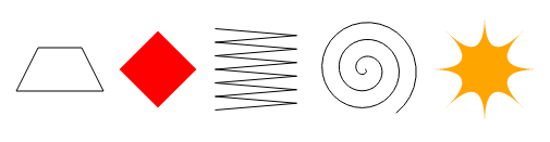
When drawing the last two shapes, you may want to refer to the explanation of Math.cos and Math.sin in Chapter 14, which describes how to get coordinates on a circle using these functions.
I recommend creating a function for each shape. Pass the position, and optionally other properties such as the size or the number of points, as parameters. The alternative, which is to hardcode numbers all over your code, tends to make the code needlessly hard to read and modify.
<canvas width="600" height="200"></canvas>
<script>
  let cx = document.querySelector("canvas").getContext("2d");

  // Your code here.
</script>
Display hints...
The trapezoid (1) is easiest to draw using a path. Pick suitable center coordinates and add each of the four corners around the center.
The diamond (2) can be drawn the straightforward way, with a path, or the interesting way, with a rotate transformation. To use rotation, you will have to apply a trick similar to what we did in the flipHorizontally function. Because you want to rotate around the center of your rectangle and not around the point (0, 0), you must first translate to there, then rotate, and then translate back.
Make sure you reset the transformation after drawing any shape that creates one.
For the zigzag (3) it becomes impractical to write a new call to lineTo for each line segment. Instead, you should use a loop. You can have each iteration draw either two line segments (right and then left again) or one, in which case you must use the evenness (% 2) of the loop index to determine whether to go left or right.
You’ll also need a loop for the spiral (4). If you draw a series of points, with each point moving farther along a circle around the spiral’s center, you get a circle. If, during the loop, you vary the radius of the circle on which you are putting the current point and go around more than once, the result is a spiral.
The star (5) depicted is built out of quadraticCurveTo lines. You could also draw one with straight lines. Divide a circle into eight pieces for a star with eight points, or however many pieces you want. Draw lines between these points, making them curve toward the center of the star. With quadraticCurveTo, you can use the center as the control point.
The pie chart
Earlier in the chapter, we saw an example program that drew a pie chart. Modify this program so that the name of each category is shown next to the slice that represents it. Try to find a pleasing-looking way to automatically position this text that would work for other datasets as well. You may assume that categories are big enough to leave enough room for their labels.
You might need Math.sin and Math.cos again, which are described in Chapter 14.
<canvas width="600" height="300"></canvas>
<script>
  let cx = document.querySelector("canvas").getContext("2d");
  let total = results
    .reduce((sum, {count}) => sum + count, 0);
  let currentAngle = -0.5 * Math.PI;
  let centerX = 300, centerY = 150;

  // Add code to draw the slice labels in this loop.
  for (let result of results) {
    let sliceAngle = (result.count / total) * 2 * Math.PI;
    cx.beginPath();
    cx.arc(centerX, centerY, 100,
           currentAngle, currentAngle + sliceAngle);
    currentAngle += sliceAngle;
    cx.lineTo(centerX, centerY);
    cx.fillStyle = result.color;
    cx.fill();
  }
</script>
Display hints...
You will need to call fillText and set the context’s textAlign and textBaseline properties in such a way that the text ends up where you want it.
A sensible way to position the labels would be to put the text on the line going from the center of the pie through the middle of the slice. You don’t want to put the text directly against the side of the pie but rather move the text out to the side of the pie by a given number of pixels.
The angle of this line is currentAngle + 0.. The following code finds a position on this line 120 pixels from the center:
let middleAngle = currentAngle + 0.5 * sliceAngle;
let textX = Math.cos(middleAngle) * 120 + centerX;
let textY = Math.sin(middleAngle) * 120 + centerY;
For textBaseline, the value "middle" is probably appropriate when using this approach. What to use for textAlign depends on which side of the circle we are on. On the left, it should be "right", and on the right, it should be "left", so that the text is positioned away from the pie.
If you are not sure how to find out which side of the circle a given angle is on, look to the explanation of Math.cos in Chapter 14. The cosine of an angle tells us which x-coordinate it corresponds to, which in turn tells us exactly which side of the circle we are on.
A bouncing ball
Use the requestAnimationFrame technique that we saw in Chapter 14 and Chapter 16 to draw a box with a bouncing ball in it. The ball moves at a constant speed and bounces off the box’s sides when it hits them.
<canvas width="400" height="400"></canvas>
<script>
  let cx = document.querySelector("canvas").getContext("2d");

  let lastTime = null;
  function frame(time) {
    if (lastTime != null) {
      updateAnimation(Math.min(100, time - lastTime) / 1000);
    }
    lastTime = time;
    requestAnimationFrame(frame);
  }
  requestAnimationFrame(frame);

  function updateAnimation(step) {
    // Your code here.
  }
</script>
Display hints...
A box is easy to draw with strokeRect. Define a binding that holds its size, or define two bindings if your box’s width and height differ. To create a round ball, start a path and call arc(x, y, radius, 0, 7), which creates an arc going from zero to more than a whole circle. Then fill the path.
To model the ball’s position and speed, you can use the Vec class from Chapter 16 (which is available on this page). Give it a starting speed, preferably one that is not purely vertical or horizontal, and for every frame multiply that speed by the amount of time that elapsed. When the ball gets too close to a vertical wall, invert the x component in its speed. Likewise, invert the y component when it hits a horizontal wall.
After finding the ball’s new position and speed, use clearRect to delete the scene and redraw it using the new position.
Precomputed mirroring
One unfortunate thing about transformations is that they slow down the drawing of bitmaps. The position and size of each pixel have to be transformed, and though it is possible that browsers will get cleverer about transformation in the future, they currently cause a measurable increase in the time it takes to draw a bitmap.
In a game like ours, where we are drawing only a single transformed sprite, this is a nonissue. But imagine that we need to draw hundreds of characters or thousands of rotating particles from an explosion.
Think of a way to draw an inverted character without loading additional image files and without having to make transformed drawImage calls every frame.
Display hints...
The key to the solution is the fact that we can use a canvas element as a source image when using drawImage. It is possible to create an extra <canvas> element, without adding it to the document, and draw our inverted sprites to it, once. When drawing an actual frame, we just copy the already inverted sprites to the main canvas.
Some care would be required because images do not load instantly. We do the inverted drawing only once, and if we do it before the image loads, it won’t draw anything. A "load" handler on the image can be used to draw the inverted images to the extra canvas. This canvas can be used as a drawing source immediately (it’ll simply be blank until we draw the character onto it).